Basic Audio Test and Measurements
This Basic Audio Test and Measurements section will cover basic testing of Cables (guitar, speaker, patch, and mic cables), Speakers, Microphones, DC Power, Fuses, Basic Amplifier audio test, and more. Learning to troubleshoot problems quickly and efficiently can save you time, and money. Warning – Always use caution when performing any type of Basic Audio Test or Measurements – Safety 1st.
 |
CHECK OUT OUR NEW “TECHNICAL” PUBLICATIONS NOW! |
 |
Getting Started
First you need to understand the difference between an “open” and a “short” before moving on to audio test and measurements…
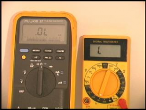
Open – An open is basically a “break” in a connection.
This is what an “open” would look like on a couple of different multi- meters.
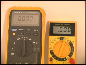
Short – A short is considered a relatively low resistance – or a direct path between two points.
This is what a “short” would look like on a couple of different multi- meters.
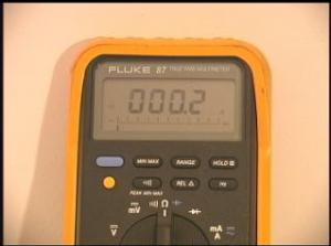
Continuity – Is basically a “continuous” path between two points (sometimes uses a tone).
What “continuity” can look like on a multi-meter. Usually the more expensive meters will have an audible tone (beep) to indicate “continuity” or a complete path.
A “Short” and “Continuity” basically look like the same measurement! But there is a difference. Think of a short as an “unwanted” path between two points – you don’t really want a short in most measurement scenarios. And think of continuity as “desired” path between two points – you are looking for “continuity” when you are testing between two points. A short can be considered part of a measurement, and continuity can be looked at as part of a test.
Example – If you are measuring a speakers impedance, and you get a “short” that would be a bad thing, because you are looking for 2, 4, or 8 ohms (whatever the speakers impedance is rated at). But, if you are testing a guitar cable, and you get “continuity” (a complete path) that is a good thing.
Opens / Shorts / Continuity Examples – Video Clip Here!
1. How to test a Guitar Cable:
Procedure for performing an audio test on a guitar / bass guitar cable (1/4”-1/4” Mono). Video Clip Below!
a) Turn the meter on, and set the meter to Ohms – the 200 or 2k (2000) setting.
b) Place the red meter lead on the tip of one end of the cable, and the black meter lead on the tip of the other end of the cable. The meter should read all zeroes (or .001 at the most – give or take), which is considered a short. This is the acceptable measurement to check continuity.
c) Next place the red meter lead on the sleeve of one end of the cable, and the black meter lead on the sleeve of the other end of the cable. Again, the meter should read all zeroes (short).
d) Now check the cable for “Opens.” Place the red meter lead on the tip of one end of the cable, and the black meter lead on the sleeve of the other end of the cable – the meter should read “open” – then reverse the leads to the opposite tip and sleeve and perform the same test (the meter should also read open – a short will indicate a failure in the cable).
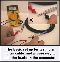
e) Then check for any shorts on each connector (see picture insert). You should read an open between the tip and sleeve on this connector. If not, check the connector for faults.
Note: Any higher than normal readings (shorts or opens) will determine if the cable is good or bad (or failing) – and will give you an idea of the reliability of the cable.
How to Test a Guitar or Bass Guitar Cable – Video Clip!
2. How to test a Speaker Cable:
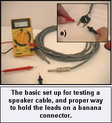
Procedure to test a 1/4”- 1/4″ speaker cable – Similar to #1 – Video Clip Below!
a) Turn the meter on, and set the meter to Ohms – the 200 or 2k (2000) setting.
b) Place the red meter lead on the tip of one end of the cable, and the black meter lead on the tip of the other end of the cable. The meter should read all zeroes (or .001 at the most).
c) Next place the red meter lead on the sleeve of one end of the cable, and the black meter lead on the sleeve of the other end of the cable. Again, the meter should read all zeroes (short).
d) Now check the cable for “Opens.” Place the red meter lead on the tip of one end of the cable, and the black meter lead on the sleeve of the other end of the cable – the meter should read “open” – then reverse the leads to the opposite tip and sleeve and perform the same test (the meter should also read open).
e) Then check for any shorts on each connector (see picture insert). You should read an open between the tip and sleeve on a connector. If not, check the connector for faults.
How to Test a Speaker Cable – Video Clip!
3. How to test a 1/4″ TRS Cable:
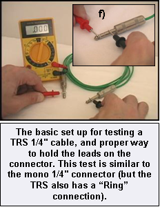
Procedure to test a TRS cable (1/4”-1/4” Stereo). Video Clip Below!
a) Turn the meter on, and set the meter to Ohms – the 200 or 2k (2000) setting.
b) Place the red meter lead on the tip of one end of the cable, and the black meter lead on the tip of the other end of the cable. The meter should read all zeroes (or .001 at the most).
c) Next place the red meter lead on the ring of one end of the cable, and the black meter lead on the ring of the other end of the cable. Again, the meter should read all zeroes (short).
d) Next place the red meter lead on the sleeve of one end of the cable, and the black meter lead on the sleeve of the other end of the cable. Again, the meter should read all zeroes (short).
e) Now check the cable for “Opens.” Place the red meter lead on the tip of one end of the cable, and the black meter lead on the ring (and then the sleeve) of the other end of the cable – the meter should read “open” – then reverse the leads to the opposite tip, ring, and sleeve and perform the same audio test again (should read open).
f) Then check for any shorts on each connector (see picture insert). You should read an open between the “tip and sleeve” (then the “tip and ring,” and then the “ring and sleeve”) on this connector. If not, check the connector for faults.
How to Test a TRS Cable / Connector – Video Clip!
4. How to test a Microphone Cable (XLR’s):
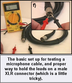
Procedure to test a Mic cable (XLR’s). Video Clip Below!
a) Turn the meter on, and set the meter to Ohms – the 200 or 2k (2000) setting.
b) Place the red meter lead on pin #1 of one end of the cable, and the black meter lead on pin #1 of the other end of the cable. The meter should read all zeroes or .001 at the most (short).
c) Next Place the red meter lead on pin #2 of one end of the cable, and the black meter lead on pin #2 of the other end of the cable. Meter should read all zeroes or .001 at the most (short).
d) Next Place the red meter lead on pin #3 of one end of the cable, and the black meter lead on pin #3 of the other end of the cable. Meter should read all zeroes or .001 at the most (short)).
e) Now check the cable for “Opens.” Place the red meter lead on pin #1 of one end of the cable, and the black meter lead on pin #2 of the other end of the cable – perform this audio test on each of the pins (pin #1 – pin #3, pin #2 – pin #3) – all should read open.
f) Then check for any shorts between the pins on each connector (see picture insert). You should read an open between the pins. If not, check the connector for faults.
How to Test a Microphone and Mic Cable – Video Clip!
5. How to test a Microphone – Using a Meter:
Procedure to test a Mic cable – Video Clip Below
a) Turn the meter on, set the meter to Ohms – the 200 or 2k setting.
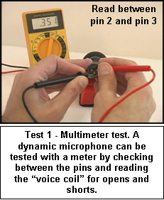
b) Place the red meter lead on the pin #2 of the mic connector, and the black meter lead on pin #3 of the mic connector. The meter should read about .350 (or close to it). If the meter reads “open” the microphones coil is most likely damaged.
* A quick and simple audio test to determine if the mic is good or bad?
Testing a Microphone with a Multimeter – Video Clip!
6. How to test a Microphone:
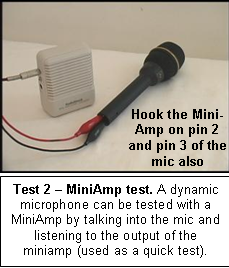
Using a Mini Amp / Powered Speaker Tester – Video Clip Below
a) Turn the mini-amp on, and turn the volume up to around 3 or 4.
b) Hook up the red mini-amp lead to pin #2 of the mic connector, and the black mini-amp lead to pin #3 of the mic connector.
c) Now talk on the mic – you should hear your voice (amplified) through the mini-amp, adjust the volume as needed. If you turn the mini-amp up too loud you may get distortion and / or feedback.
* This is the fastest audio test to determine if the mic is good or bad?
Testing a Microphone with a Powered Speaker – Video Clip!
7. How to test a Speaker:
Procedure to properly test a speaker. Video Clip Below!
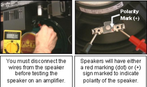
a) Turn the meter on, set the meter to Ohms – use the 200 setting.
b) Place the red meter lead on the speaker terminal marked with a red dot or marked with a (+) sign, and the black meter lead to the speakers other terminal.
c) What should the meter read? This depends on the speakers impedance (resistance). You can find the speakers impedance on the back of the speaker (see picture insert). If the speaker impedance says 8 ohms, then your reading could be anywhere from 6.1 ohms all the way up to 8.4 ohms (give or take). A 16 ohm speaker could read anywhere from 12.4 all the way up to 18.2 (give or take). Any reading within these guidelines can indicate that the speaker is good.
Notes: If you read an “open” when measuring speaker impedance, then the speaker is defective. If you read 2 ohms on an 8 ohm speaker, this could be a sign that the speaker is failing.
Testing a Guitar Amplifier Speaker – Video Clip!
8. How to test DC Power – Batteries:
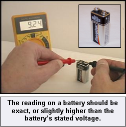
Procedure to test batteries (all DC batteries). Video Clip Below!
a) Turn the meter on, and set the meter to DC Volts / 20 volt setting.
b) Place the red meter lead on the positive (+) terminal of the battery, and the black meter lead on the negative (–) battery terminal. The meter should read 9.0 (or higher for a 9V battery).
How to Test a 9-Volt Battery (any battery) – Video Clip!
9. How to test a DC Power Supply:
Procedure to DC power supplies. Video Clip Below!
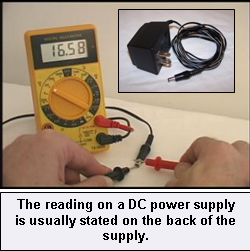
a) Turn the meter on, set the meter to DC Volts / 200 volt setting (to start).
b) Plug the DC power supply into a wall receptacle (use caution).
c) What is the voltage of the power supply? Find this on the back of the power supply – should read 5VDC, 12VDC, 15VDC, etc.
d) Place the red meter lead on the positive (+) terminal (usually the center conductor), and the black meter lead on the negative (–) terminal.
Ex: Meter reading should 15 volts or higher for a 15V supply.
How to Test a DC Power Supply – Video Clip!
10. How to test Fuses:
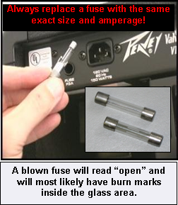
Procedure to test Fuses – PROCEED WITH CAUTION! – Video Clip Below!
a) Turn the meter on, and set the meter to ohms (use the 200 or 2k setting).
b) Important: Remove power from the equipment (unplug power cord from wall) prior to performing this audio test).
c) Remove fuse (shown)
d) Place the red meter lead on one end of the fuse, and the black meter lead on the other end. The meter should read a “short” (all zeroes or .001 for a good fuse).
How to Test a Fuse (any fuse) – Video Clip!
11. How to test Headphones:
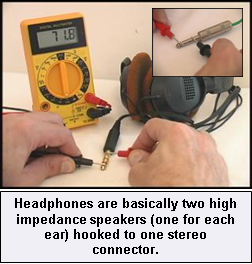
Procedure to test a set of headphones, uses either a 1/4″ or 1/8” TRS. Video Clip Below!
a) Turn the meter on, and set the meter to Ohms – the 200 or 2k (2000) setting.
b) Place the red meter lead on the “tip” of the connector, and the black meter lead on the “ring” of the connector. The meter should read anywhere from 50 ohms up to 80 ohms (depending on the set of headphones) – this is the total impedance of the headphones – the starting point for the following audio test.
c) Place the red meter lead on the “tip” of the connector, and the black meter lead on the “sleeve” of the connector. Now the meter should read around “half” of the total impedance (Example: If the total impedance read in c) was 60 ohms, you should now read around 30 ohms – half of 60).
d) Now place the red meter lead on the “ring” of the connector, and the black meter lead on the “sleeve” of the connector. Now the meter should read around “half”of the total impedance (Example: If the total impedance read in c) was 60 ohms, you should now read around 30 ohms – half of 60). The reading all depends on the reading you get in b – which is the total impedance).
e) If you read a “short” (000 or .001) or an “open” on any of the tests above then the headphones are defective (could be both sides or just one side).
How to Test a Set of Head Phones – Video Clip!
Conclusion
This Basic Audio Test and Measurements menu page should enable you to test the majority of the practice equipment, and gear that you use in your studio or in your band. Again, always use safety and caution when performing an audio test and / or troubleshooting any type of equipment.

BASIC AUDIO TEST EQUIPMENT INFO HERE!
